Sunday, 17 February 2013

Project 2 - PART ONE: Weblog journal entries


Final Project 2

1. Character 

My robot name is Jerry.

Jerry work scope is stacking up stock boxes, he works from Monday to Friday, 8a.m to 6p.m daily and he have to stack 5000 of boxes each day. His workplace is at Woodland and he lives at Tampines, which he spends 2 hours in travelling back and forth. He wake up at 5.30a.m each morning and will only reach back home at 8p.m.

This 2 weeks is the hot season week as it is Chinese New Year festival so Jerry have to work everyday from Monday to Sunday at the same timing, he do not have any off days. Today is the 8th day that Jerry had been working consecutively.

Current situtation

Is going 6p.m now, Jerry is feeling so exhausted, he is so lacked of sleep nowadays that every morning he always face challenge of waking up. All he is looking forward to, is finish stacking the 5000 boxes. The more boxes he stacked, the more tiring he feels. Each time, he has to force himself to bend down his arm and stack the boxes. This thought "How many more is left to stack..." had been going through Jerry's mind umpteen times.

2. Storyboard 


3.   Self-Critique 

I am quite happy with my final result. As everything goes according to plan even thou the process of doing it is not easy and I faced some difficulties completing it. The problem I faced are, time management, adjusting the key frames, animating the emotions of the robot and the stretch and squash technique. However, after a couple of times of trial and error and also seeking help from my classmates and teacher, I managed to do all the requirements!

The most important things to do in this project is the key-framing and animating emotions. For example, Jerry is feeling exhausted so the speed of picking up the boxes will definitely be slow as he is tired so the time frame in between before he pick up the box and when he pick up the box will be a long period of time.

As for the emotions of the robot, at the start the Joint4 is all the way facing down when he picks up the 2 boxes in front, so after he picked up the 2nd box, I adjust the Rotate X wanting to show the emotion of the robot sighing. It give the impression of looking up to sigh then look down again, as if saying that "How many more..."

Lastly, I added the stretch and squash technique to the ball to make it look more realistic. As in a real ball in will all stretch and squash when it is hitting something. Squash is used when it is hitting something and stretch is used when it bounce off.

So, that's all for my Project 2!

Sunday, 10 February 2013

Week 12 Exercise 1 - Beach Ball Animation


Firstly, set a new project so that this beach ball will have its own document folder. Next, set the preferences which is the default settings and the change the size of the grid.

Next, create a ground using the polygon primitives and select at the 200 value. Now, choose the NURBS primitives and scale the ball to 15. Move the boxes and enclose the scene and now I can hide the camera.

Create a camera for rendering. Go create > camera > camera & aim. After that, add the resolution gate so that it chooses the place where you put to see, outside the resolution gate, nothing will be chosen. Now, I assign new material to the ball by when i right click it and go to assign new material > blinn. Change the setting attributes and choose create render node and choose 2D texture and ramp. Next, assign new material for the ground also. After assigning, now I add a bump map.

Next, to animate the ball, station the ball out of the camera view, rotate the ball and freeze the transformations. Go into the graph editor and edit it using break tangents to edit individually and now the ball is bouncing smoothly.

To make a squash & stretch effect, create deformers > non linear > squash. Go under attribute editor and the "Factor" determines the effect. Now, link the squash handle to the ball. Click on the squash handle then the ball and press "p". To set the key frame, I just select keyframes and and it. To manage the time of the animation, I can use dope sheet and manipulate it. Window > animation editors > dope sheet.

To add lighting, create > lights > directional lights. Then move the light out of the ground and rotate it to whichever lighting suits. Choose the ray trace shadows then change the shadow to grey. Now the ball has a dark side so to make it look better, choose ambiance lights and put it below the ground.

Final Product:

Week 14 - Digital Character Animation


For the video above, it is the Anticipation. The video shows a person process of kicking a ball.
The reason why it is suitable for Anticipation is because, it show a person natural way of gaining momentum before an action (kick the ball) begins. A natural way of gaining momentum in this video is, the person slowly lift out her leg to kick the ball.


This video is about Creating Holds. Creating holds mean keeping a pose on the screen for a specified period of time. In this video, the person hold a ball for a period of time before placing it down on the floor. Similarly, the person waited for a short period of time before picking up the ball again.


This video is Follow-Through. Follow-Through is when a character comes to a stop, not every part of the body will stop at the same frame. In this video, the person stop in a position but her hair is still flying/moving.

This video is Overlap. For overlap, it is similar to Follow-Through but the different between them is that in Overlap, it happens during the motion while in Follow-Through, it happens only at the end of the motion. In this video, when the person let off the ball, it first bounce and continue bouncing till a stop.

This video is Squash and Stretch. For Squash and Stretch, it simply means the object will change it shape as you apply force to it. In this video, the person first squash the ball using force then the ball will stretch off by to it original shape when the force is removed.

This video is Secondary Action. For secondary action, it means that after the primary action, secondary action will happen. For example, in this video, the primary action is the person throwing a ball but as she throws the ball, her hairs and jacket are both moving so this is the secondary action we are talking about.

Monday, 4 February 2013

Week 13 - Exercise 4


Pixar Short: Luxo Jr. HD

1)  Apart from their different sizes, it is obvious from Luxo Jr. that the big lamp is “older” and that the small lamp is “younger”. 

How is this communicated by the animation? Give at least THREE examples.
Do NOT say because the small lamp is playing with a ball, or that its name is Luxo Jr. – you should be looking at the animation, how the lamps move and emote (emote means to express emotions).


Apart of their different sizes, here are 3 examples that show the big lamp is "older" and that the small lamp is "younger":
  1. When the ball first hit on the big lamp, it did not play with it but instead it kick the ball away.
  2. When the big lamp saw the small lamp playing with the ball, it did not really join in the fun but just look at the small lamp playing with it.
  3. The big lamp is calm unlike the small lamp which is playful. In the last part, it end with the big lamp shaking it head when it saw the small lamp found another new big ball to play with as if saying that the small lamp never learn it action.
2)  Give an example from Luxo Jr of how timing is used for comic effect. Explain how the timing decisions contribute to the humour.

At 1.25, the small lamp start to walk off after bursting the small ball but after 8 seconds, in 1.33, the small lamp came back with a big ball! The timing is just right, it wasn't too long nor short. In 1.25, many of the viewers might have think that it is the end of the video but just as we thought it gonna be the end, the small lamp came back which kinda of surprised the viewer pleasantly!

Also, in 1.31, it shows that the big lamp is looking at the small lamp which is at the other side of the room but after 2 seconds later, in 1.33, the big lamp flip up, giving off the shock and surprised that the small lamp came back with a much bigger ball! The effect given is funny and cute as well ^^

3)   When you create a joint chain, these form a hierarchy, with the first joint at the top and the last joint at the bottom. Explain why this is necessary for the joints to work properly.

I had mentioned in Week 13 - Exercise 2 post, the order of selection is important. You want to select the child node first, and then Shift-select the item that will become the parent node second. It is because it will follow the same direction of where it is moving from the first joint at the top till the last joint at the bottom. In another word, the joints below the top first joint will follow the movement of the top joint!

This Week 13 exercises is quite manageable just that it is a bit tedious to do but overall, it is interesting and fun! Specially, the Pixar Short: Luxo Jr HD youtube video! The video is cute and it make the exercises more interesting as well! ^^

Week 13 - Exercise 3


1) Animate the box moving at a linear speed past the robot.

2) Animate the crane lifting the box. 

For both video, it is just about moving and placing the model and box and set it at the timeline. It is a easy and fun exercise, it can be finished in less than an hour! It's a interesting experience to see how your Maya work can turn into an animation video.

Sunday, 3 February 2013

Week 13 Exercise 2

In this exercise 2, we are given instructions from http://download.autodesk.com/us/maya/2011help/index.html?url=./files/Inverse_kinematics.htm,topicNumber=d0e17823 we can just follow the instructions at the website and do it step-by-step. As this is still something new to us, our teacher was there to guide us when we are doing this exercise.

First, we open up the file of IK_MechArm.mb then in the next step is to do the hierarchical relationship between the model and the IK system. Hierarchy means "A system or organization in which people or groups are ranked one above the other according to status or authority." - information taken from https://www.google.com.sg/search?hl=en&tbo=u&biw=1280&bih=685&q=hierarchy&tbs=dfn:1&sa=X&ei=MjsOUdujFMrVrQf-4oDYCQ&ved=0CCoQkQ4

In Maya, hierarchies are structured in a top-down manner, with one node at the top (the parent node or root node) and other nodes (child nodes or leaf nodes) attached and interconnected beneath the top node.


The benefits of hierarchies is when we are selecting the parent node at the top of the hierarchy, it selects the items contained in the hierarchy below. When we are selecting a child node lower in the hierarchy, it selects any child nodes that are lower in the hierarchy. Also when the parent node of the hierarchy moves, the rest of the model (child nodes) also moves. It helps us save a lot of trouble when we are doing complex structures with relationships between components.


To view the hierarchy for the mechanical arm, use the Hypergraph (Panels > Hypergraph Panel > Hypergraph.).


One of the first step we did was, create a skeleton hierarchy. From the main menu, select Skeleton > Joint Tool. The Tool Settings window for the Joint Tool appears. The Joint Tool is used to create the joints and bones for a skeleton.


Then, click in the center of each pivot pin on the mechanical arm to place four joints as shown in the image above. When we are done with the placement of the last joint, press Enter to indicate that the last joint has been placed.


When we are done, it will appear as the image shown above. In the Hypergraph, when we select the joint1 node, the entire skeleton becomes selected but if we only select joint2, any rotations that we make on this node affect only joint2 and nodes below joint2 which does not include joint1 (above joint2).


The next step is Parenting a model into a skeleton hierarchy. First, in the Hypergraph, select the node named ArmEnd and Shift-select the node named joint4 then in the main menu, select Edit > Parent (Hotkey p). Take note: The order of selection is important. You want to select the child node first, and then Shift-select the item that will become the parent node second.


The next step is Applying IK to a skeleton hierarchy. The key point of IK is to allows users to control the joint rotations in a skeleton using an IK handle. From the main menu, select Skeleton > IK Handle Tool, click on the skeleton joint at the base of the mechanical arm and click on the skeleton joint at the tip of the mechanical arm like the image above (left). In the Hypergraph menu, select View > Frame All. In the Hypergraph, two new nodes appear in the hierarchy that represent the IK chain: an IK Handle node and an end effector node as shown in the image above (right).


Then, create a control object for an IK system as using the IK Handle to pose an IK chain is not a good practice.  The IK Handle can be challenging to select in the scene view, a better practice is to create a control object. In the Hypergraph, select the ArmControl node then in the main menu, select Create > Annotation, a input window will appear. Type in ArmControl and click OK. In the scene view, the word ArmControl appears near the locator/control object. In the Hypergraph, two new nodes appear in a hierarchy beneath ArmControl as shown in the image above.

Before
After

Next, constraining an IK system meaning constrain the IK Handle to the control object (ArmControl) using a point constraint. A point constraint allows the transformation attributes of one object to be controlled by the transformations of another object.


Then, limit the range of motion of an IK system. Limit the range of motion of the arm to ensure that the IK system poses in a predictable manner. Lock the Translate X channel for ArmControl and lock the Rotate X and Z channels for SwivelBase. To lock, right click on the specific box then a drop-down menu will appear. From the drop-down menu, choose Lock Selected and it will be in dark blue color as shown in the image above.


The number of nodes in the IK system’s hierarchy at this point is way too long and it can be quite confusing so now, we have to simplify the display of the hierarchy. In the Hypergraph, right-click on joint1, and choose Collapse from the pop-up menu. The child nodes below joint1 disappear, simplifying the display of the hierarchy. The small arrowhead on the corner of the joint1 node indicates that a hierarchy exists below joint1. If you later need to view or select these nodes you can expand them again by right-click and click on expand.


Now, we apply parent constraints on an IK system. In the Hypergraph, with ArmControl still selected, Shift-select the CargoBox node. Take Note: The order of selection is important when you apply constraints. You must select the constraining object first, and the item to be constrained second.
In the main menu, select Constrain > Parent. Now, CargoBox is constrained to ControlArm. A new constraint node has been created below the CargoBox node in the Hypergraph. If you reposition the mechanical arm, CargoBox moves with it because of the constraint that is now applied.

Finally, we are done with this exercise! Next up will be doing an animtaion for an IK system. This exercise took 2 lessons to complete. It is quite long and tedious but it is a new learning experience for us!

Tuesday, 29 January 2013

Week 13 Exercise 1

Pixar Short: Luxo Jr. HD
http://www.youtube.com/watch?v=zmhZm5FRV4s

 I find this video interesting and cute. In this video, is about animation of 2 table light - a big and small one, playing around balls - small and big. What makes this video interesting is because, the way it is animated, it brings out a story.
For example, in the picture above (0:23), the way it is animated seems that the table light is "looking" at the small ball in a curious way. As if the table light is saying "What is this?", as the big table light is blending down and looking at the small ball in a funny way.

Also, in the picture above (1:02), the small table light is hopping on top of the small ball happily, it keep jumping non-stop. While the big table light is looking at the small table light, in a curious? envy? way, as if it can't wait for it turn to play with it.

The sounds played at the background also play a important part to the video. It make the video look more interesting and also the sounds played at the background are matching with the action of the table lights. For example, in 1:05, when the small table light burst the small ball, it give off the air-busting sound which allow the user to hear and understand that the ball is burst.

To conclude this exercise, I understand that in Maya, we can also do animation and we can do something similar to what we had seen in this video. This video might be short, but it can be seen that there are a lot of efforts used to do the animation. From modelling to rendering and sound etc, I hope that in future, I will be able to do such animation video in Maya as well!

Saturday, 19 January 2013

Week 12 Exercise 2

1)Do you need to be able to draw well to create good 2D animation? Explain your view.

We do need some drawing skills (doesn't have to be extremely good in drawing) to create a good 2D animation. As by drawing the model out, we will understand the model more and also be able to visualize the model out.

 2) Do you need to be able to draw well to create good 3D animation? Explain your view.

Similarly to question 1, I think that we do need to have some drawing skills to create a good 3D animation, to help us to visualize the model.  As it can helps us in knowing better of which shapes to use or what techniques skills to use. But we do not have to draw really well to create a good 3D animation, just being able to draw out the basic outline of the model will do.

 3) What do you think would separate a piece of poor animation from a piece of good animation? In other words, how would you go about deciding if a piece of animation is good or bad?

I think the most important point in judging a piece of poor animation and a piece of good animation is the realism of the model. If the model look realistic and look as real as the object model itself, it is counted as a piece of good animation. As it will be able to let the user recognize the object instantly without having any doubts. 

 4) In 2D animation, you need to be very aware of timing at a frame by frame level, using timing charts and other techniques - but for 3D animation, this is handled using the graph editor, which is more concerned with manipulating rates of change over time.
 Does this affect how you approach your animation work? Explain.

It does not affect much when I am approaching my animation work. The graph editor helps us draw the arcs and curves, but definitely we still need to change the graph by using the tangents available to make it look perfect. Also, we still need to key in key-frame in specific timing which means frame-by-frame basis is still being used. So overall, it did not make much changes.

 5) Give a brief critique of Maya as an animation tool. Don't just say Maya makes animation difficult, or easy, or that you need to learn a lot of stuff to use Maya - explain what Maya does well and not so well in terms of creating animation.

Maya is a good animation tool, it might seems hard to use at first but as you get to learn about the basic of Maya, it is quite easy to use and adapt to it. Also, Maya does a good job in creating animation by having convenience technique for us to use when we are creating the model. For example, the graph editor. By just seeing the graph editor and adjust the tangents accordingly, we can make the model's movement look more perfect and realistic.

However, in Maya, when we are creating more complex model, it is difficult for us to do it in Maya. One of the problem we faced, is regarding the shapes. As there are only limited shapes available for us to use, some shapes that we need does not include in Maya so we can only have to find similar or close to shape to replace it which change the original form of the model.


Week 11 Lab 2

1) Why is squash and stretch so useful in animation?
   
     By having squash and stretch, it add on a more realistic feeling to the bouncing ball which shows that it is really bouncing off the ground. Without the squash and stretch, the bouncing ball will just look like a stiff metal ball jumping (not bouncing) around as only a metal texture ball won't be able to squash and stretch.

Without the squash and stretch effect
With the squash and stretch effect

2) Think of a situation in which extreme squash and stretch could be applied to a character - try to be original.

Extreme squash and stretch could be applied to a character that is being slapped. As when one person is being slapped, the face will first be squash, it happened as when the hand using force to smack the face. Then it will stretch after the slap as the skin will stretch back to it original form.

3) Think of an animation example where squash and stretch would NOT be appropriate

Like I mentioned in question 1, metal texture item would not be appropriate for squash and stretch as it is not flexible and cannot be blend! Same goes to all the hard materials, example: Steel, wood, glass etc.

4) If squash and stretch doesn't really happen so obviously in real life, why do you think is it so effective in animation? 

Squash and stretch doesn't really happen so obviously in real life because it happened too fast, so we are no able to see. But it is effective in animation because in animation, it was played in a slower speed also, in animation it create a illusion that gives off a realistic feeling to the user. 


Week 11 Lab 2

First, we create the polygon sphere then at the main tab click on Window -> Outliner and ctrl+g twice.
Then renamed the groups names to prevent confusion and enable us to recognize which is which.
Next, select the translate_ball_gp group and Create Deformer -> Nonlinear -> Squash. If you did not see the Create Deformer in the main menu tab which means you are not in the Animation module. So change it to Animation module before this step! If you have done this step correctly, you will see handle named “squash1Handle” created (in the Outliner).
Then, we will parent the squash1Handle to the translate_ball_gp group. Firstly, select the handle, then press control and select the translate_ball_gp group in the Outliner. Next, press the p key(release control) to parent the handle to the group. If you have done this step correctly, it should look like what is shown in the image I included above.
The next step will be locking up the channel attributes as we do not want any changes made and to also avoid accidentally changes. 

To lock the channel attributes, select the wanted ones by using the shift or control and the left mouse button (LMB). Then right mouse click and a long list of selection will appear. Choose the Lock Selected. This action will lock all the selected channels and no change can be done to them.

If you have done this step correctly, the locked ones will be in blueish color while the unlock ones will be in red color. It should look like what is shown in the image I included above.
The next step will be mainly changing the factor value (at the squash1Handle) at different time of the timeline to change the effect to squash and stretching to the ball. To insert timeline, click on s.

A positive value in the Factor will create an exaggerated stretched ball. 
A negative value in the Factor will create an exaggerated squashed ball.

As the ball falls to the ground, it will be stretched by gravity. As the ball hits the surface, it will be squashed because of the impact on ground. To let the ball regain its normal shape, the squash1Handle’s Factor is 0. 
Rotation the value of the ball to point your stretched ball in a particular axis (in this case, the Rotate Z value) so that it would seemed to be bouncing in a stretched manner towards that direction.
Lastly, to animate the Rotation of the ball, select the rotate_ball_gp group. At Frame 1, set a keyframe with the Rotate Z value of 0. Then set a keyframe at Frame 100 with a Rotate Z value of -1200.
Extra : I changed the ball color and put in color for the plane by right-click on the object and click on assign new material -> lambert.


To conclude this exercise, it is more tedious then Week 11 Lab 1 exercise, it is more challenging and I have to extra careful with the timeline and all the numbers. Also, I often make the mistake of not keying s after the challenges I made in the values. 


Friday, 18 January 2013

Week 11 Lab 1


When we first open the Keyframing.mb file, this is what the file had already included. 
The tennis ball and the tennis court. To make the tennis court bigger, we change the pPlane1; scale x, y and z to 100, in order to let the green plane occupy the whole screen.
Next, we will adjust the tennis ball. At different timeline, we change the value of translate x and y accordingly to have the effect of the ball bouncing up and down.

Translate x set the tennis ball movement front or back. The higher the value, the tennis ball move nearer to the end of the tennis court, similarly, the lower the value, the nearer to the start of the tennis court.

Translate y set the tennis ball closeness to the ground. The higher the value, the tennis ball further to the ground, similarly, the lower the value, the closer to the ground.

To key in into the key-frame press s after setting the value of translate x and y at the channel box/layer editor.

Be careful of the timelines we picked on as we won't want the ball to jump too slow or too fast. It have to look real and realistic so we have to try and error the different timeline!
The tennis ball bounce up.
When the tennis ball is bouncing up, the translate y value should be high so as to stay away from the ground.
The tennis ball bounce down
When the tennis ball is bouncing down, the translate y value should be low so as to be near to the ground.

Single bounce
Double bounce

Overall, this exercise is fun and interesting as this is our first time making a video out of Maya! Also, the exercise is manageable as there are step-by-step tutorial available! Lastly, I feel that this exercise make us realized there are a lot more we can learn and do in Maya! 

Sunday, 6 January 2013

Week 7 to Start of Term 2


Project 1 – Part One

1.   Story

The object that I modeled is Ferris wheel.

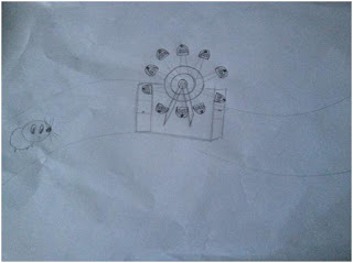
The story is about a rat racing around a track on a mousetrap car. In the middle of the track, the ferries wheel will be place there.

The rat has to go pass the Ferries wheel in order to continue the race. As the rat enter in the Ferries wheel at the front, it will turn one round of the Ferris wheel and then back to the base of the Ferris wheel where the rat will exit. After the rat exit the Ferris wheel, it will continue the race and complete the track racing.

The purpose of the Ferris wheel is to acts as a road block so that it will be more difficult and challenging for the rat to complete the race. As the Ferris wheel is placed at the middle of the track, there is no way that the race can avoid it. So in order to complete the race, the rat has to go through the Ferris wheel.

 
Diagram on the rat race

2.   Shape

My toy model – Ferris wheel

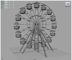
For my toy model, it is mainly made up of circles, cylinders and torus. As the Ferris wheel are made up of repeated shapes. For example, the cabins so we can just create 1 cabin and just duplicate it. Then using the move tool, shift and rotate the duplicate shape to place it in the right place.


Parts of the Ferris wheel

The cabins of the Ferris wheel have windows so we have to extrude it. First, we create a circle then we use cube to extrude the windows out.

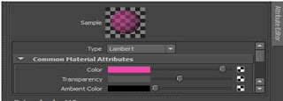
 Also you can see from the picture, the cabins color is not strong, is more like a transparent color so, we just have to adjust the transparency level.

Maya – Common material attributes
3.   Design

Drawings
Front view of the Ferris wheel

 
Front view of the cabin

Maya Progress

 
1st week – Axis of the Ferris wheel

2nd week – Building up of the Ferris wheel without the base

3rd week - Front of the Ferris wheel, without coloring

4th week – Front of the Ferris wheel with coloring

5th week – Back of the Ferris wheel

5th week – Side of the Ferris wheel

4.   Research

 
Before coloring

After coloring


Leo Tsang also created a Ferris wheel model on Maya. Similarly, he had duplicated the various shapes throughout the model to form the Ferris wheel.  Also, texturing was involved to make the model to look more real by adding texture and colors to it.

He not only models the Ferris wheel, he also makes the Ferris wheel to be able to rotate, using grouping and centering pivot point of the main wheel. This makes his Ferris wheel look realistic. Which is more advance and I can try to do the same if I’m done with the modeling of the Ferris wheel to challenge myself.


5.   Self-Critique
Original model

  Maya model

For my final model, I think that it look quite similar to the original model. The Maya model is not exactly the same as the original model but it gives off similar impression of the original model.

The main problem I have when I am doing the Maya model, is the shape of the cabins, the base and the middle pointy shapes. Other than these problems, I found the rest of the modeling process is manageable.

Below, I will further elaborate on the success and problems I faced.

Left - Original, Right - Maya cabins

As you can see from the left picture, the original cabins are made up of a flat-looking base. It seems to be made up of a rectangle as a base and circle at the top. But for my Maya cabins, I only used circle shape to make it which is not quite similar to the original ones. However, for the Maya windows are quite similar to the original windows of the cabins.

Left - Original and Right – Maya, Back of the Ferris wheel

In my Maya Ferris wheel cabins, I used up similar color in compared to the original Ferris wheel. Also, the number of cabins (10) I made in the Maya is the same number of cabins (10) in the original. In order to make the Maya model as realistic as the original model, we have to include all the details available.

Left - Original and Right – Maya, Detail of the back of the Ferris wheel

For example, for the back of the Ferris wheel, I also do it as the same as how the original model is. It is important to be as detailed as possible as if I did not do the back stander in Maya, it will not make sense. As there have to be a back stander to support the Ferris wheel.

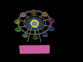
Left - Original and Right – Maya, Middle pointy shapes

This is the most difficult part of the modeling. I used the concept we learnt in the Gear exercise (Week 2 Lab 2 Part 2). First, I create a pipe then adjust the size I want it to be. Right click it and click on Face, click on the sides of the pipe to extract the pointy shape out. It is not quite successful but I managed to make slightly pointy triangles shape out. The reason why it was not successful as when we are doing the Gear exercise, the size we extracted is rectangle which is much easier to adjust the shape out.

The second challenge I faced for this part is after I am done with the Gear part, I have to do blue shapes and diamond (yellow) shapes out. It is extremely difficult to create the shape as well as alight it accordingly as it is in the original model. After much trying, I am still not able to do it hence; I replaced it with a basic triangle shape.

     Conclusion

To conclude, after doing this project, it let me have a better understand of how to use certain tools in Maya. It also gives me more chances to try out different tools and give me more experience to use it.

Also, by doing this project, it make me realized that, items that we see daily, can be model in Maya as well. It also make me realized that, we are capable to model those cartoons characters we see in movies which makes me feel more interested in 1N3D as there is so much more we can do in this subject.

Project 1 – Part Two
Bonus Extras
1)    Lighting


2)    Texture-Mapping - Rust Metal 

Front view of texture-mapping

Back view of texture-mapping